![]()
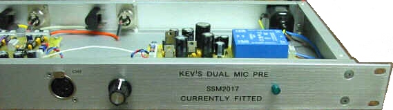
KDMP - Kev's
Dual Mic Pre in
a rack box
![]()
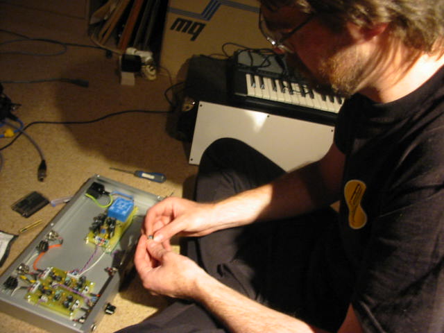
A friend needed a simple
to operate Mic-pre to suit an AM3 card ...
(This project had zero budget and AMIII card is on load from me and our friend
has zero expertise so this is whole project is based on low cost and simplicity
of use).
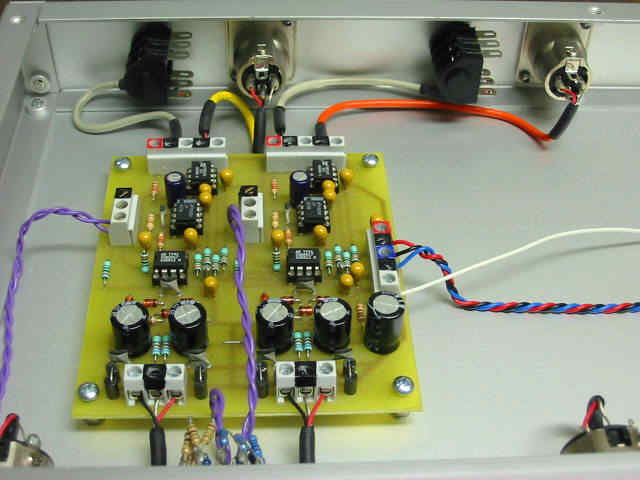
The KDMP was originally designed for battery operation to record effects and dialog for video. All on a single PCB it has balanced mic input with both unbalanced and balanced +4dB output. The mic section is an SSM2017 and the set up is straight from the Analog Devices application notes. The output is via a trusty LM833 dual op-amp. This provides the unbalanced output and also buffers and adds a little gain to the signal and on to the SM2142 balanced line driver chip. Some diode protection around the front end saves the SSM2017 when condenser mics are plugged and unplugged. That's it ... simple. The hard design and setup work has been done by the chip manufacturer. As such this has no bias adjustments or tweaks to do. It is reliable, consistent and a good all round workhorse.
I chose the KDMP for this project as I did already have a drilled PCB lying around and had some SSM2017 chips ready to go. See the note below about the discontinuance of the SSM2017 chip. I had also recently received some samples of both the new SSM2019 and the older INA217. This made for a good opportunity to check out the differences between the various chips. It also gave me the push needed to put my thinking towards the powers supplies I have been promising to Group DIY for some time now.
This KDMP had a couple of cap changes at the input. The phantom blocker caps have been changed to 100uF 63V, which is in line with the Green-Pre. I hope to also take the opportunity to compare the KDMP with a Green-Pre. There is likely to be very small differences in phase shift between a standard KDMP and this one and also the Green-Pre. If I get time and equipment I hope to display the results here.
The fastest way to get this going was to use my usual Elgee rack box with the extruded front panel. The KDMP has both balanced and unbalanced outputs and I decided that both were usable for this situation. Both of these would be on the back panel as usual. Not so usual for me is to mount the inputs on the front panel. This should suit my friend's method of operation. In the future, when it is completed, they will have the new DAW Monitoring Switcher. Both the outputs of the mic-pre will be used, the unbalanced will feed the Switcher and provide hardware monitoring while in record and the Balanced output will feed the main input, perhaps via a normalled patch point.
It had been decided that metering would not be required for this situation, the metering in Alsihad (ProTools) would do that job well enough. I should point out, that this person is new to recording and so the simpler and easy it is to use the better. In line with this thinking the gain controls will be rotary switches so that a setting can easily be recalled and keep recordings consistent from session to session. Consistent layout and levels in a session makes life so much easier for me when it comes to mixing their demos into a masterpiece.
The KDMP doesn't allow for independent switching of phantom power and in keeping with simplicity it was decided to have phantom permanently ON. If this becomes a problem I can instal a single switch to operate both channels. It is just as likely that phantom could end up remaining permanently OFF. If they only have a single Shure 58 then phantom will not be needed.
All that is now left to do is come up with an appropriate power supply.
![]()
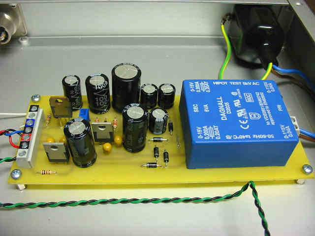
The following is a few thoughts on what is required and involved to design a power supply to suit.
The KDMP requires +/-
15volts to18volts and phantom volts for Condenser Microphones.
Current consumption at idle (two channels) is approx. 45mA per rail.
The number of different components should be as few as possible and should be
easy to obtain. For example, instead of specifying both a 10uF and 22uF cap
I will use two 22uF caps, the number of different items on the parts list will
be fewer. Instead of using a PO4 bridge rectifier, I'll use four IN4001 diodes,
easy to obtain. Less wiring, so mount as much as possible on the PCB. A PCB
mount power TX may be the only difficult part to obtain. The one I chose for
this project is a 6VA unit from Farnell. Two 15v secondary windings at 0.20mA.
7815 and 7915 voltage regulators will handle the main rails. These regulators,
with heat sinks are good for at least 1amp so with a larger power TX and some
heatsinks this basic layout could supply much more.
Borrow the phantom circuit from the G9 Tubed Mic-pre for the phantom power.
It is a voltage doubler technique to obtain sufficient volts from the 15 volts
AC to regulate down to the required 48volts. This is adjustable with a trim
pot. The regulation is done with a cheap TIP121 or 122 transistor, again this
should be easily obtained.
![]()
 _
_ _
_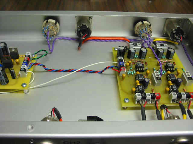
If you are wondering
what the white wire is and why it is long and tucked under the power
supply ...
I had originally intended to have a Phantom On/Off switch on the front panel
and this is long enough to do the job if I later change my mind ... again.
![]()
For more info on power supplies, try Group DIY's Power Supplies page.
![]()
SSM2017 . discontinued
but I hope we will have an obvious alternative soon. INA217 or THAT1510.
... and now Analog devices have a replacement ... SSM2019.
Kev's
Dual Mic-pre
Schematic
![]()
A comparison of sorts.
I have had some samples lying around the workshop for a while. We do like Product Samples here at Group DIY. During a recent recording session I took the oportinity to test these new samples. I have used these circuit boards on many occasions but this was the first time I had a number of different replacement IC's on hand to check out. These IC's included some INA217's and a couple of SSM2019's and more SSM2017's..
 _
_ 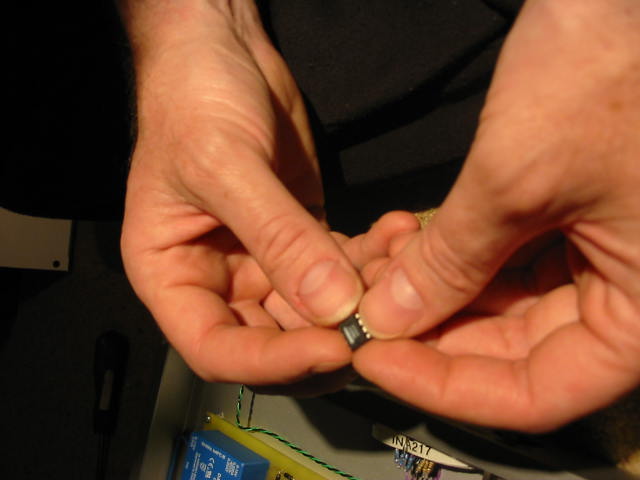
I tried a couple of methods to separate the sound of these chips. The first and obvious method was to record sequential takes using a different chip for each take. This was time consuming and didn't give a clear indication as each take was fresh and separate by more than a few minutes. It was possible to hear some sort of difference but is too difficult for me explain with any clarity what was going one. So as I am lazy at the best of times and eager to get a result quickly I employed a few less than perfect methods. I had a couple of microphones of the same brand and model so I decided that it might be interesting to use a pair of mics but with a different chip in each channel on the mic-pre. Record one take and compare the sound. Theory is that, only the chip has changed. Yeah I know, there is two microphones and even if they are sequential serial numbers they are not the same as they are not a matched pair. The mic-pre's circuit and components will also l have variances but as this is a real word comparison and not meant to be a lab test, I decided to push on. We do expect to be able to use these things as a stereo pair and as such, I think this is a worthwhile test.
The results by now where a little better and we could identify some differences between the chips. Basically we did sequential vocal takes and swapped a single chip each time. Leaving the first channel untouched as the reference chip. The reference chip was an original SSM2017 that I have had for many years. It has had some use but I am satisfied that it is one of my good examples of this unit. We compared this to other SSM2017's and then to some INA217's and lastly the new SSM2019. Comparing each chip to the reference chip one take at a time, differences in the sound could be heard and also could be seen on the waveform of the DAW. As I said, not a lab test by any means but valid enough to try to form some sort of conclusion.
Still not satisfied that the differences were not caused by the variances in the two mics, perhaps low frequency response and in particular the slight phase shift when comparing two SSM2017's I chose to try one last method. The hard core mic boys should close their ears now. Yes, the dreaded Y cord was employed. Using a single microphone to drive two mic-pres would take these variances out of the equation. Sure the incorrect loading of the microphone may cause some issues but .. get over it. The 2017 to 2017 comparison was now very close and I felt satisfied that the two channels were performing to the same standard. We could now compare the reference chip to the other two chips.
By now you are probably hoping for some definitive answer to which chip is better. Well I'm going to disappoint you. As this is a budget unit and we only did a vocal test with the voice of a single person, it is not fair to give the nod to a clear winner. When one chip was better in one area it was a little weak in another. Please note that these differences were very subtle and I think it fair to say these chips are good replacements for each other. I still have my favorite (could be that I am just so used to hearing it) but the other two faired well enough that I would be happy to use them in the future.
If you are thinking of starting a project that uses the SSM2017 and you are having trouble sourcing some then do go for the SSM2019 or INA217 as I don't think you will be disappointed.
" Kev , did you
just put them into some sort of order ? " ... oops
![]()
more to come,
![]()
THAT
Corp
have anounced there equivalent to the SSM2019
THAT1510
![]()
![]()
Brought to you by Kev